

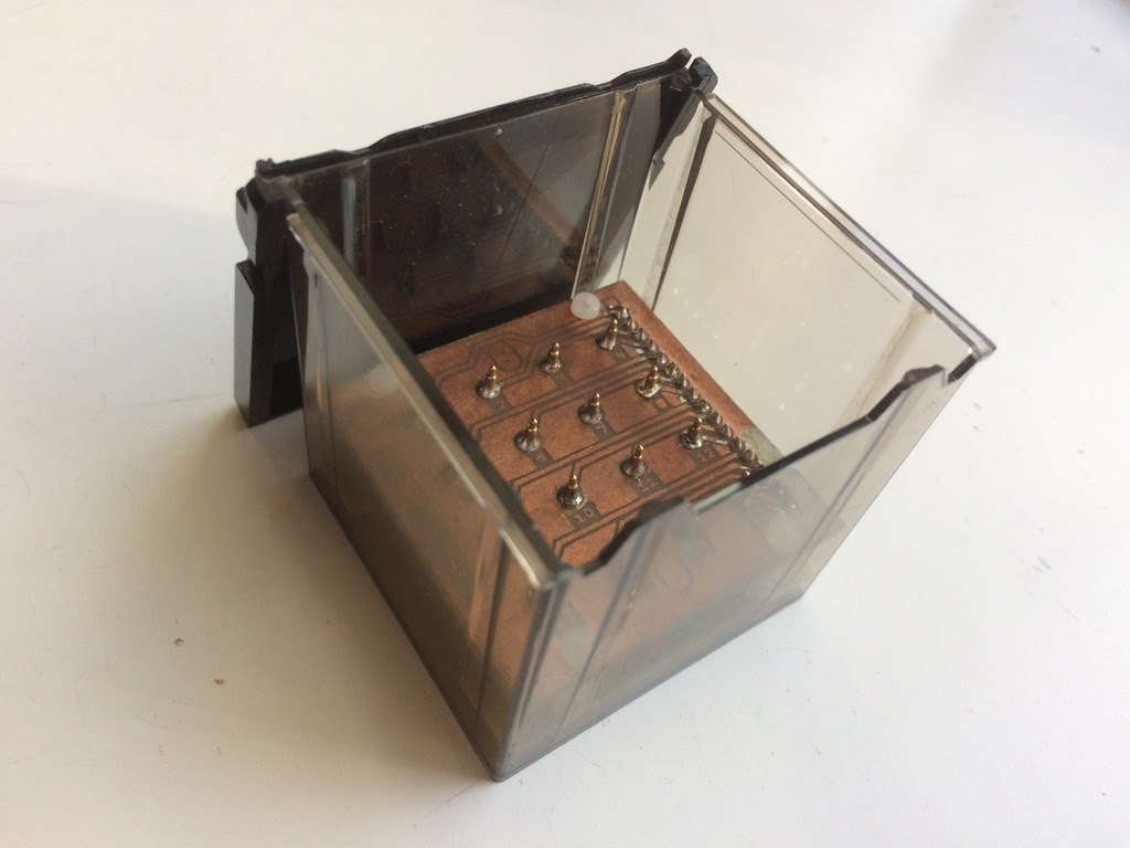
A photographic slide viewer can be used as an electronic device enclosure. The hopper of an “automatic” slide viewer will hold a stack of 2x2in (5x5cm) standard photographic slides.
The Socket4by4 is a connector specification that uses that hopper space for a peripheral.
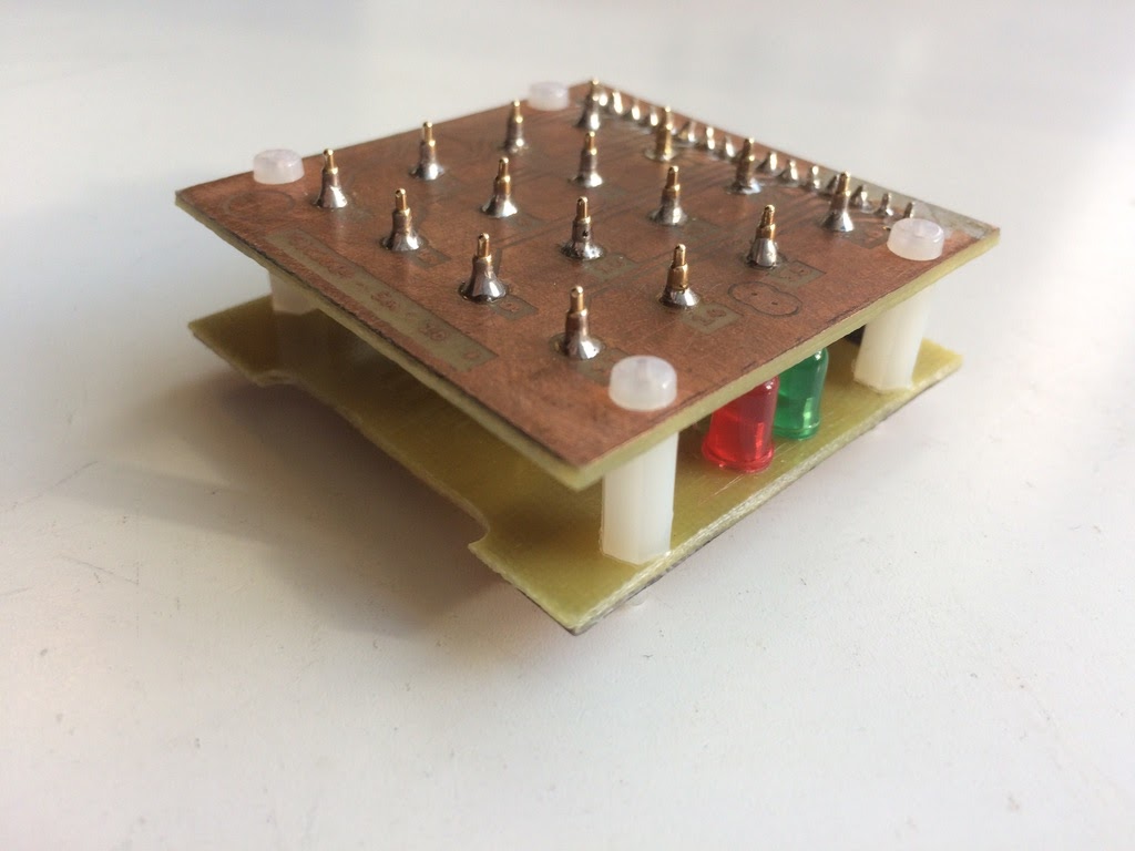
The connector receptacle is a square grid of 16 pins. The plug is a single conductive plane. The pins are grounded when the plug is in contact with the receptacle. Pin patterns define number values, and covering contact points on the receptacle produces different values. Using this peripheral for input produces up to 256 individually identifiable objects.
An example plug would be a 2 inch (5x5cm) cube, such as a toy wooden block. The back would be covered with a metal plate or conductive tape. The pin pattern for each block can be defined with small pieces of insulating tape or paint. A cube can accommodate 6 values, one for each face. Alternatively, if labels are used on the upward face, opposite of the plug face, then 3 values can be accommodated on a cube.
Connector
Plug
The Plug is electrically a single conductor to Ground. Contact with the Plug is on a 4x4cm grid of 16 points. The two middle rows of pins represent eight (8) bits in a binary number. Three corner points are masked to create an orientation. The fourth corner point is Ground, and the point next to it is the voltage source. When these two pins connect through the conductor of the Plug, unmasked pins are pulled LOW. The default unmasked BITs value is 255 (FF in hexadecimal, or 11111111 in binary).
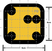 | A contact point will conduct if clear, but not if masked. A cell produces a LOW signal when clear. A cell produces a HIGH signal when masked. The top-right corner (P0) and the point to its left (P1) must be clear to conduct power. The remaining three corners must be masked to establish Orientation. The two middle rows of points represent the 8 Bits. A clear Bit is LOW. A masked Bit is HIGH. |
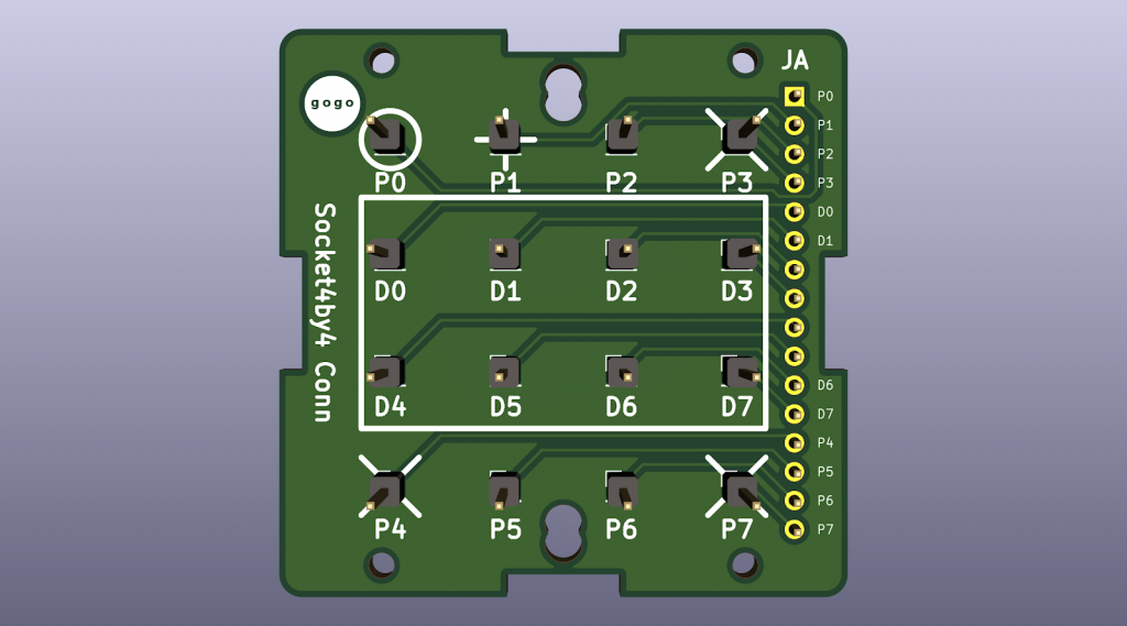
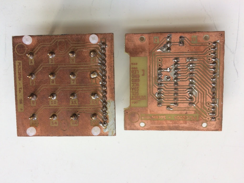
Receptacle
The Receptacle consists of a grid of spring-loaded pins, each wired individually. The corner pin P0 is pulled down to Ground. The P1 and P2 pins detect connection and parity, while the BIT pins represent the numeric value of the Plug. The other three corner pins enforce orientation, and must be masked on the Plug.
| P0 | Ground | GND |
| P1 | /CONNECT | Input |
| D0 – D7 | Bits | Input |
| P3,P4,P7 | Orientation | VCC |
| P2 | Parity Bit (odd) | Input |
| P5,P6 | Unused |
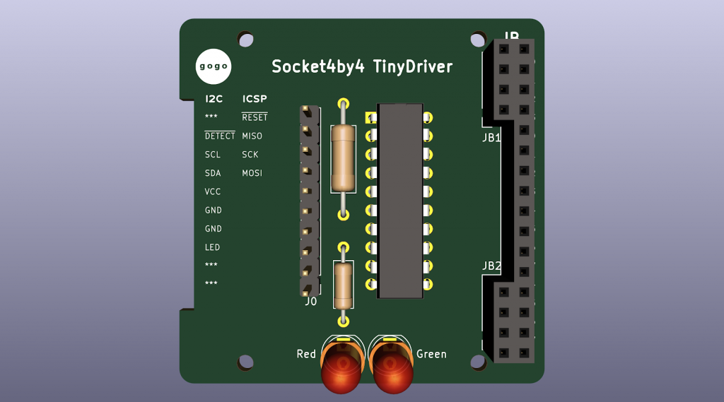
Hardware Driver
The hardware driver consists of the Receptacle, a dedicated MCU, and all the connections between them. The MCU would have BUS connections for serial data communication.
MCU
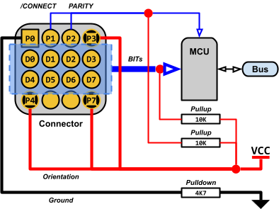
The MCU configures /CONNECT with an input pin and a 10k pullup resistor.
The MCU configures PARITY with an input pin and a 10k pullup resistor.
The MCU configures BITs each with an input pin and a 10k pullup resistor.
Connector
Corner pin P0 Ground is configured with a 4k7 pulldown resistor, connected to GND.
Corner pins P3, P4, P7 are connected to VCC.
P1 is connected to /CONNECT.
P2 is connected to PARITY.
Bus
The MCU writes the BITS data to the Bus.
Connector Operation
When P1 is connected to P0 through the Plug, /CONNECT is pulled LOW, indicating a connection is made.
When an Orientation pin is connected through the Plug, the entire Ground plane is pulled HIGH, indicating an incorrect orientation.
The BIT and PARITY inputs are pulled HIGH by the MCU. A BIT or PARITY input connected through the Plug becomes pulled LOW.
Parity is odd, since there are 8 BITs. The P2 point on the Plug must be masked if there is an odd number of masked BITs.
A Plug with only the Orientation pins masked has a default value of 255 (FFh), including parity.
When the Plug is connected in the correct orientation:
- /CONNECT is active LOW.
- BITs are active LOW.
- PARITY is active LOW.
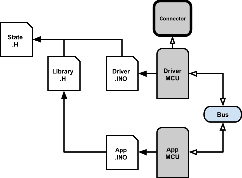
Firmware Architecture
The Driver MCU reads the Socket4by4 Connector and sends the State through the Bus.
An Application MCU gets the State through the Bus.
Application
Socket4by4 I2C Driver With ATtiny2313
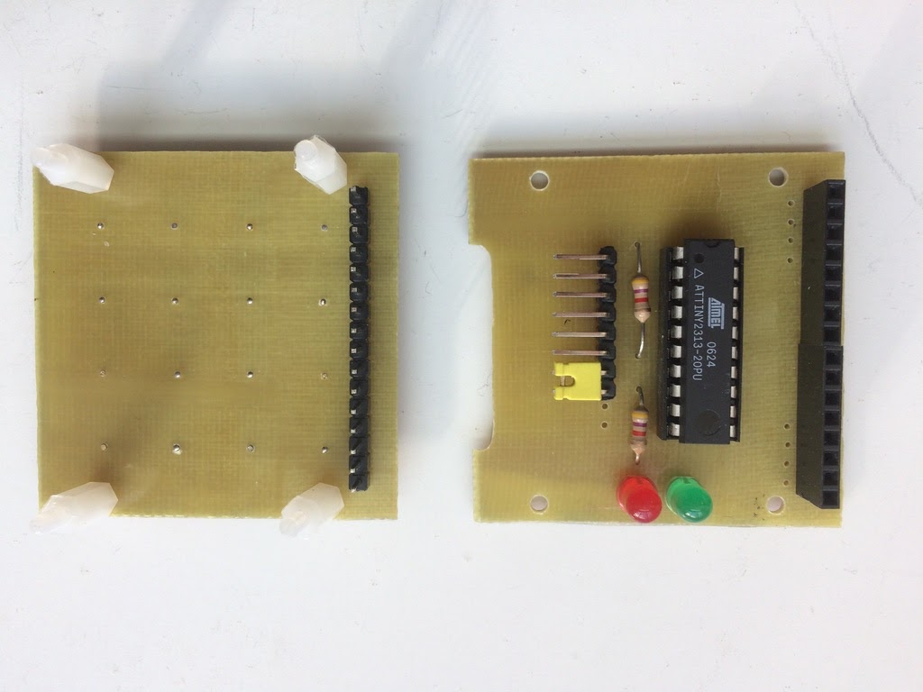
The Driver MCU is an ATtiny2313. The Bus is I2C. The Application is an Arduino Uno.
The ATtiny2313 is wired to a Socket4by4 Receptacle through eight (8) GPIO pins dedicated to the Data BITs, one GPIO pin dedicated to /CONNECT, and one GPIO pin dedicated to PARITY.
The ATtiny2313 has built-in 10k pullup resistors.
Two LEDs, red and green, are wired in parallel with a 4k7 resistor to indicate the Connector status, including activity and error. Ground is wired with a 4k7 pulldown resistor.
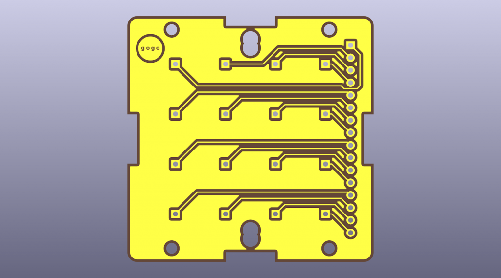
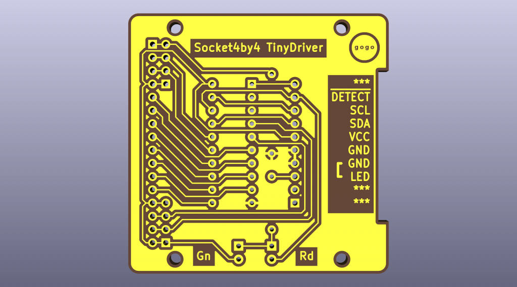
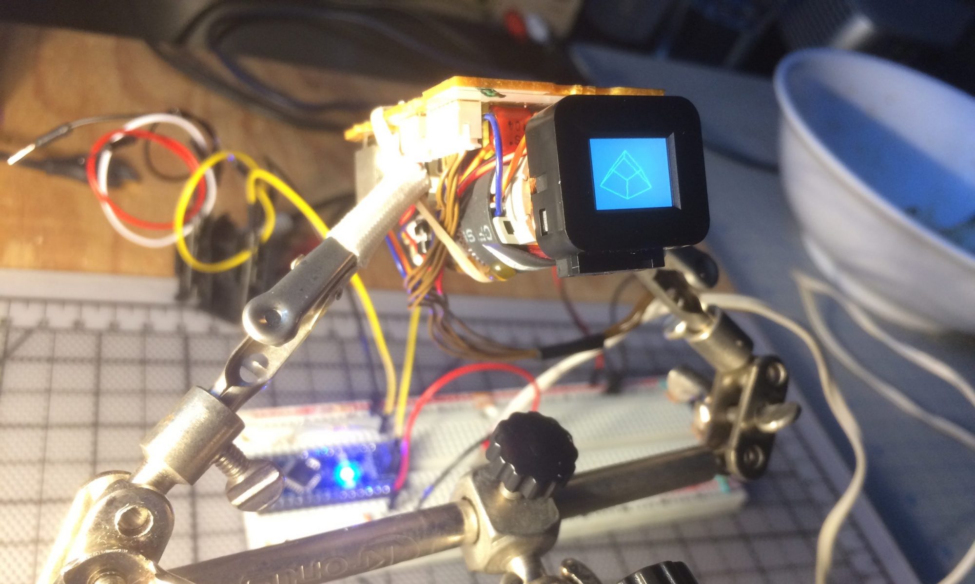
Receptacle Prototype
State Definition
Socket4by4.h
This file defines the State of a Socket4by4 Connector.
// (c) gogo
// Socket4by4
#ifndef Socket4by4_h
#define Socket4by4_h

namespace Socket4by4
{

////////////////////////////////////////////////////////////////////////////////
// !!! minimum code size is critical !!!
class Info
{
public:
  enum Status
  {
    NC            = 0x00,// no connection
    Error         = 0x01,// parity error
    DebounceBegin = 0x02,// debounce start
    DebounceEnd   = 0xff,// debounce done
    OK            = DebounceEnd,
  };

  uint8_t status;             // state, includes debounce progress
  uint8_t bits = 0b11111111;  // the data bits

  bool connected()    { return status != Status::NC; }
  bool error()        { return status == Status::Error; }
  bool ok()           { return status == Status::OK; }
  // debounce progress
  uint8_t debounce()                { return error() ? 0 : status; }
  void debounce( uint8_t progress ) { status = progress & ~Status::Error; }

  // -1 if out of bounds
  int read( int i )
  {
    if ( i == 0 ) return status;
    else
    if ( i == 1 ) return bits;

    return -1;
  }

  void write( int i, uint8_t c )
  {
    if ( i == 0 ) status = c;
    else
    if ( i == 1 ) bits = c;
  }
};

};// namespace Socket4by4

#endif// Socket4by4_h
Driver INO
Socket4by4_ATtiny2313_I2C.ino
This Arduino Sketch is a Socket4by4 Driver firmware that runs on the ATtiny2313.
The MCU reads the State of the Socket4by4 connector pins.
The Socket4by4 State is transmitted on the I2C bus.
// (c) gogo
// Socket4by4 driver
// ATtiny2313
// I2C
// !!! minimum code size is critical !!!

// Connector pins
// P0 P1 P2 P3
// D0 D1 D2 D3
// D4 D5 D6 D7
// P4 P5 P6 P7
//-
// P0       - Ground
// P1       - Connect
// P2       - Parity (odd)
// D0-D7    - Data Bits (8x)
// P3,P4,P7 - VCC
// P5,P6    - (unused)
//-
// MCU inputs (P1,P2,D0-D7) have 10k pullups.
// P0 (ground) has a 4.7K pulldown.
//-
// P1, and D0-D7 are pulled down when connected to P0; all inputs go LOW.
// P3,P4,P7 (orientation) pull everything up to VCC; all inputs go HIGH, i.e. disconnect.

// Operation
// Check for connection; P1 is LOW.
// Start debounce timer if connected.
// Stop debounce timer if disconnected.
// Read BITs each frame when connected.
// Error if BITs change during debounce.
// Error if parity mismatch.
#ifndef Socket4by4_ATtiny2313_I2C
#define Socket4by4_ATtiny2313_I2C
#ifndef ARDUINO_AVR_ATTINYX313
  #error The current platform is not supported.
#endif
#include <Socket4by4.h>
#include <util/parity.h>

// I2C
#include <Wire.h>
#define I2C_address 8

// connector pins
// ATtiny2313
// P0              // ->4k7->GND
// P3,P4,P7        // ->VCC; orientation
#define Pin_P1 13  // ->GPIO+10kPU
#define Pin_P2 12  // ->GPIO+10kPU
#define Pin_P5 3   // unused
#define Pin_P6 2   // unused
// D0-D7           // data bits 0-7
#define Pin_D0 4   // ->GPIO+10kPU
#define Pin_D1 11  // ->GPIO+10kPU
#define Pin_D2 5   // ->GPIO+10kPU
#define Pin_D3 10  // ->GPIO+10kPU
#define Pin_D4 6   // ->GPIO+10kPU
#define Pin_D5 9   // ->GPIO+10kPU
#define Pin_D6 7   // ->GPIO+10kPU
#define Pin_D7 8   // ->GPIO+10kPU
#define Pin_Connect  Pin_P1  // /CONNECT; active LOW
#define Pin_Parity   Pin_P2  // PARITY; odd
const int8_t pin_D[ 8 ] = { Pin_D0, Pin_D1, Pin_D2, Pin_D3, Pin_D4, Pin_D5, Pin_D6, Pin_D7 };

// indicator outputs
#define Pin_Detect 15  // DETECT active LOW. == MISO to match ICSP/SPI programming pins, because unused for I2C

// poll rate
#define FPS_ms (100)                                // time between polls
#define Debounce_ms (1000)                          // debounce (scan) progress; 0xff == 1 second
#define Debounce_tick (0xff / (Debounce_ms/FPS_ms)) // fraction of 0xff to inc each frame

#define IsPulse( ms, hz ) ( hz ? 1 & ( ms * hz / ( 1000 / 2 ) ) : 1 )// flasher; div by 2 = 50% duty
unsigned long tickMs;
unsigned long scanMs;
Socket4by4::Info info;
uint8_t oldBits;


void setup()
{
  // I2C
  Wire.begin( I2C_address );
  Wire.onRequest( OnRequest );

  // connector
  // P1 (/CONNECT) active LOW
  pinMode( Pin_Connect, INPUT_PULLUP );// pullup is required
  // P2 (PARITY)
  pinMode( Pin_P2, INPUT_PULLUP );// pullup is required
  // D0-D7
  for ( int i = 0; i < 8; ++i )
    pinMode( pin_D[ i ], INPUT_PULLUP );// pullup is required

  // indicator
  pinMode( Pin_Detect, OUTPUT );
}

void loop()
{
  // FPS
  unsigned long ms = millis();
  if ( tickMs < ms )
  {
    // connect
    bool newConnected = digitalRead( Pin_Connect ) == LOW;// active LOW

    // CONNECT did change
    if ( info.connected() != newConnected )
    {
      // did connect
      if ( newConnected )
      {
        // initial reading
        Scan();
        oldBits = info.bits;
        // start debounce
        info.status = Socket4by4::Info::Status::DebounceBegin;
        scanMs = ms + Debounce_ms;
      }
      else
      // did disconnect
        info.status = Socket4by4::Info::Status::NC;
    }

    // connected
    if ( info.connected() )
    {
      // debounce in-progress
      if ( !info.error() && !info.ok() )
      {
        Scan();

        // still debouncing
        if ( ms < scanMs )
        {
          // BITs are still the same
          if ( oldBits == info.bits )
            info.debounce( min( Socket4by4::Info::Status::DebounceEnd, info.debounce() + Debounce_tick ) );
          else
            // ERROR; BITs changed
            info.status = Socket4by4::Info::Status::Error;
        }
        else
        // debounce done
        {
          // parity
          bool parity = digitalRead( Pin_Parity ) == HIGH;
          parity = parity == !parity_even_bit( info.bits );// odd parity
          // ERROR; parity mismatch
          info.status = parity ? Socket4by4::Info::Status::OK : Socket4by4::Info::Status::Error;
        }
      }
    }

    // FPS
    tickMs = ms + FPS_ms;
  }

  Draw( ms );
}

////////////////////////////////////////////////////////////////////////////////

// read the data pins
void Scan()
{
  // each pin
  for ( int i = 0; i < 8; ++i )
    bitWrite( info.bits, i, digitalRead( pin_D[ i ] ) );
}

// display status
void Draw( unsigned long ms )
{
  // indicator
  if ( info.debounce() )
    // pulse while debouncing, or connection ok
    digitalWrite( Pin_Detect, ( info.ok() || IsPulse( ms, 10 ) ) ? LOW : HIGH );// active LOW
  else
    // pulse while error, or solid while no connection
    digitalWrite( Pin_Detect, info.error() ? ( IsPulse( ms, 1 ) || IsPulse( ms, 20 ) ? HIGH : LOW ) : HIGH );// active LOW
}

// I2C request
void OnRequest()
{
  int i = 0;

  while ( true )
  {
    int c = info.read( i++ );

    if ( c >= 0 )
      Wire.write( c );
    else
      break;
  }
}

#endif// Socket4by4_ATtiny2313_I2C
Arduino Library
Socket4by4_I2C.h
This file defines I2C Bus communication with an I2C Socket4by4 Driver.
// (c) gogo
// Library for Socket4by4
#ifndef Socket4by4_I2C_h
#define Socket4by4_I2C_h

#include <Socket4by4.h>
#include <Wire.h>

namespace Socket4by4
{

////////////////////////////////////////////////////////////////////////////////
// Call begin() with the address of the device to be read.
// Call read() to read the bits from the device.
class I2C
{
public:
  Socket4by4::Info info;
  int i2cAddress;// must match the driver

  void begin( int i2cAddress )
  {
    // I2C
    this->i2cAddress = i2cAddress;
    Wire.begin();
  }

  // true if connected has changed
  bool read()
  {
    bool wasConnected = info.connected();
    int i = 0;

    Wire.requestFrom( i2cAddress, 2 );
    while ( Wire.available() )
    {
      info.write( i, Wire.read() );
      ++i;
    }

    return ( info.connected() != wasConnected );
  }

  float progress()   { return (float)info.debounce() / (float)Socket4by4::Info::Status::DebounceEnd; }
};

};// namespace Socket4by4

#endif// Socket4by4_I2C_h
Arduino Application Example
Test_Uno_I2C.ino
This Arduino Sketch tests communication with an I2C Socket4by4 Driver.The Socket4by4 State data is displayed through Serial output.
// (c) gogo
// Example: Read Socket4by4, output to Serial
// I2C
#define I2C_Address 8// must match the driver
#include <Socket4by4_I2C.h>
Socket4by4::I2C socket4by4;

// poll rate
#define FPS_ms 100
unsigned long tickMs;
bool progressDone;

void setup()
{
  Serial.begin( 115200 );
  socket4by4.begin( I2C_Address );

  Serial.println( "\nSocket4by4 test started." );
}

void loop()
{
  unsigned long ms = millis();
  if ( tickMs < ms )
  {
    if ( socket4by4.read() )
    {
      progressDone = false;

      if ( socket4by4.info.connected() )
      {
        Serial.print( "[SCAN] " );
        Serial_printData();
        Serial.println();
      }
      else
        Serial.println( "[-NC-]" );
    }

    if ( socket4by4.info.connected() )
    {
      if ( !progressDone )
      {
        Serial.print( "[SCAN] " );
        Serial.println( socket4by4.info.debounce() );
        if ( socket4by4.info.ok() )
        {
          progressDone = true;
          Serial.print( "[-OK-] " );
          Serial_printData();
          Serial.println();
        }
        else
        if ( socket4by4.info.error() )
        {
          progressDone = true;
          Serial.print( "[-ERR] " );
          Serial_printData();
          Serial.println();
        }
      }
    }

    tickMs = millis() + FPS_ms;
  }
}

void Serial_printData()
{
  Serial.print( "0x" );
  Serial.print( socket4by4.info.bits >> 4, HEX );
  Serial.print( socket4by4.info.bits & 0xf, HEX );
  Serial.print( " = " );
  Serial.print( (int)socket4by4.info.bits );
}